The ArcSolTM panel is a high-ratio concentrating photovoltaic (CPV) system that functions in a fixed position. The panel encloses an array of identical two-axis self-orienting CPV elements embodying several innovations that maximize the transmission of radiant energy entering the panel to the solar cells. This paper estimates the energy conversion efficiency of the panel by examining the various losses encountered by light and then electrical energy as it passes through the system, starting with sunlight encountering the panel's front face and ending with the electricity conveyed on the panel's output wires.
The present method estimates the panel's conversion efficiency by multiplying the separate efficiencies of the series of factors listed in the following outline. The factors are listed in roughly the order that they are encountered by energy as it progresses through the system.
In the analysis below, each of these factors is examined and assigned a loss ratio value, expressing the ratio of energy lost at that stage to the energy that entered that stage. Subsequently, the efficiency values, each being the complement of its respective loss ratio, are multiplied together to obtain an estimate of the panel's energy conversion efficiency.
The present method makes some simplifying assumptions to generate a single scalar-valued efficiency estimate. Like efficiency ratings based on PV panel nameplate power ratings, the present estimate assumes that the panel is illuminated by sunlight aligned with the panel's normal axis. Furthermore, the estimate does not consider the spectral distribution of different loss modes.
Although panel efficiency is generally described as a scalar quantity, it is more accurately described as a function whose domain is a portion of the two-dimensional space of light incidence angles. That function is rarely examined for PV panels, whose energy conversion efficiency remains relatively flat for incidence angles of up to 40 degrees. For smaller angles, the output remains roughly proportional to the aperture, which varies as the cosine of the incidence angle. The same function is far from flat for many CPV systems, whose area efficiency is greatly diminished in portions of the incidence-angle space due to gaps in light-capture coverage. In contrast, the ArcSol panel has consistently high light-capture efficiency, as well as a wide range of tracking motion, and consequently has a relatively flat efficiency function that can be approximated by a scalar quantity. The present analysis characterizes incidence-angle-dependent factors individually, but uses average quantities to compute a representative efficiency value.
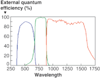
The concentrator cells used in the ArcSol panel convert radiant energy over a broad band of the visible and infrared spectrum -- from about 350 to 1600 nanometers (nm) of wavelength. That band is covered by the overlapping absorption spectra of the cells' three stacked PV junctions. Losses in the optical system that are not balanced between the junctions' absorption spectra can result in a loss of efficiency greater than the loss of radiant energy. Apart from the cells' spectral sensitivity, loss modes with different spectral distributions can produce net losses that are not captured by reducing each efficiency factor to a scalar value. A refinement of the present method would characterize each efficiency factor that has a non-uniform spectral profile as a vector representing loss magnitude as a function of wavelength, and multiply those vectors to obtain a vector representing net spectral efficiency. Fortunately, the ArcSol panel's loss modes that have non-uniform spectral profiles are relatively flat and are well-approximated by scalar values.
The following analysis attempts to enumerate all of the significant factors that determine the total energy conversion efficiency of the ArcSol panel -- the ratio of the radiant energy flux reaching the panel's front face to the electrical power available on the panel's output wires. Because these factors are sequential and probabilistically independent, their individual efficiencies can be multiplied to give the total conversion efficiency. For clarity, each factor section ends with an estimated loss ratio, whose complement is the factor's efficiency,
The first obstacle encountered by a ray of light incident upon the panel is its interaction with the pane of cover glass, where energy is lost due to surface reflections and absorption by the glass. The glass is assumed to be a type of fused silica.
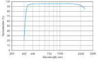
The light transmittance efficiency of a material is typically specified as a function of light wavelength for a sample of some thickness such as 10 mm, where the sample is illuminated by light perpendicular to its face. This measure of efficiency is the product of factors which are often not specified separately: an interface transmittance factor, which describes how efficiently light passes to and from the material, an internal transmittance factor, which is describes how efficiently light passes through the material. The first factor is the much more significant of the two and is more complex, being a function of not only wavelength, but of incidence angle and of the material's refractive index. This analysis separates these two factors in anticipation of developing more detailed characterizations of each separately.
Light passing through the cover glass encounters two interface transitions: first from air to glass, then from glass to air. At each transition, a fraction of the energy is lost by reflecting off instead of transmitting through the interface. That fraction is highly dependent on the light's incidence angle on the cover glass' surface, and is relatively low up to such angles of about 45 degrees. Because the optical index of most glasses varies somewhat by wavelength, the interface transition efficiency is a function of wavelength, but a gradual one.
A small fraction of energy is lost through absorption by the glass itself. This loss is proportional to the material's thickness, is a function of electromagnetic wavelength, and is very minor for most pure glasses from about 400 through 1500 nm. Glasses can be engineered to have steep increases in absorption at certain wavelengths. By filtering wavelengths below 300 nm, the cover glass can protect the interior parts from UV radiation.
Once a ray of light passes through the cover glass it either falls upon a CPV element's optic, or misses any such optic and strikes some portion of the panel base, converting most of its energy to heat. The probability that it reaches such an optic, called the light capture efficiency, is a function of the geometry of the elements within the panel and can be computed with precision based on a model. The potential loss can be either of two types: losses due to coverage gaps around the panel's periphery; and losses due to coverage gaps in the array's interior.
Because the ArcSol CPV element optics do not tile to the edge of the rectangular space defined by the panel's enclosure, there are coverage gaps around the panel's edges that measure up to on-half the diameter of a single optic.
For a given size of CPV element, the relative area of these gaps varies inversely with the panel's linear dimensions. The following formula estimates the area of the boundary gaps relative to the area footprint of the array as a function of the number of rows and columns in the array:
| relative-gap-area = | number-of-rows / 2 + number-of-columns * taper-ratio |
| number-of-rows * number-of-columns |
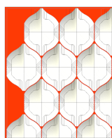
In the formula, the taper-ratio is the fraction of a reflector's profile area that is flanked by curved outer edges. That ratio is about 0.4 for reflectors having an elongation ratio of one, as pictured to the right. The present estimate assumes a 1.06-meter-by-1.6-meter panel that houses a 10-column by 15-row array of ArcSol elements, giving a relative-gap-area of (15/2 + 10*0.4)/(10*15) or 0.077. That estimate describes the loss when the sun is aligned with the panel's normal direction. For non-zero incidence angles, this loss ratio decreases -- particularly given that the panel's side walls are transparent -- and becomes insignificant for such angles approaching 45 degrees. The present analysis uses an aggregate value of one-half the boundary gap ratio for the panel-normal light direction to approximate the average behavior over incidence angles up to about 40 degrees.
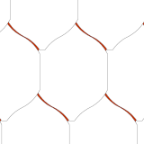
Light falling on the interior of the array may be lost by passing through coverage gaps between adjacent elements and thereby evading capture by the optics. The sizes and shapes of these gaps is a function of the light's incidence angle and corresponding orientation of the CPV optics, and of the shape of the optics within the aforementioned one-parameter family.
This simulation shows that the inter-element capture gaps in an array of oriented elements never exceeds three percent, and weighted average over incidence angles is probably close to one percent.
Having traversed the cover glass and dodged the coverage gaps between and around the CPV optics, our intrepid light ray next encounters the pivotal juncture of its journey to the PV cell: reflection by a paraboloid mirror surface within the ray's capturing CPV optic. In contrast to the optics of most other reflective CPV designs, which use two-stage optical systems, the ArcSol panel focuses light on the PV cells using only a single reflection.
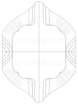
The OptifoldTM reflector used by the ArcSol CPV element is a novel reflector geometry that eliminates occlusions within the reflector's aperture by embedding receivers within the risers in the reflector body parallel to the direction of incident light. The profile view of the reflector pictured on the right shows the paraboloid mirror surfaces provide compete coverage of the profile, whereas the riser surfaces that bound those mirror surfaces are foreshortened to infinitely-thin edges. This geometry allows the cells, their mounts, and additional heat sinks, as well as the arc that supports the assembly, to be mounted underneath the reflector and within its volume of motion, entirely out of the path of incident light.
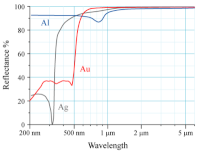
When light encounters the reflector surface, a certain fraction will be absorbed by the materials comprising that surface. The magnitude of this absorption is a function of the light's wavelength, and is largely determined by the intrinsic reflectivity of elements making up those materials. The ArcSol panel calls for the application of a thin film of silver, among other materials, to the mirror surfaces, where silver has an intrinsic reflectivity of more than 0.9 above 450 nm and more than 0.95 above 700 nm of wavelength.
Light that is reflected by a paraboloid mirror surface will either reach or not reach the receiver, depending on the accuracy of the angle of reflection. The reflector surface is shaped to bounce directional light striking any portion of a reflector quadrant to a spot within the PV cell mounted in the opposite quadrant. Although the overall shape-accuracy of the reflector is unlikely to be an issue in its focusing, small-scale imperfections in the mirror surfaces will cause a certain fraction of the reflected light to fall outside of its target cell, and be lost to energy production. This loss, which we call surface scattering, is defined for the present discussion as any reflected ray of light where the dot product of its incidence and reflection angles departs from the mirror surface normal by more one degree.
Although the present analysis breaks down reflector surface losses into surface absorption and surface scattering, these two factors can described as the complement of the surface specular reflectivity -- a quantity that is frequently measured for reflectors.
The preceding discussion of reflector losses assumes that the optic is oriented so that its normal axis coincides with the direction of incident light. A divergence from that alignment by as little as two degrees will cause a loss of focus on the receivers and almost complete loss of energy conversion. Devising a closed-loop algorithm to keep the light maximally focused on the receivers is not difficult, but maintaining the mechanical alignment between direction sensors and the optics is an issue in many CPV system designs. The ArcSol CPV element avoids such alignment issues by autonomously tracking using the PV cells as the light direction sensors.
The ArcSol CPV elements use triple-junction Group III-V cells designed to convert highly concentrated atmosphere-attenuated sunlight to electricity with the highest possible efficiency. The performance of these cells have been described in some detail by their vendor -- one of several companies specializing in concentrator cells. The cell specifications provide detailed data on cell efficiencies at a set of standard test conditions, and plot efficiency with respect to variables such as temperature, concentration ratio, and incidence angle -- variables whose standard test condition values favor efficiency. The present approach starts with a reference efficiency factor -- the specified cell efficiency under standard test conditions -- and adds several additional factors to capture reductions in conversion efficiency due to less-than-optimal operating conditions.
The cells used in the ArcSol panel have a mean energy conversion efficiency at specified test conditions of 40 percent. Those test conditions are favorable for cell performance in several ways, including: an operating temperature of 25ºC, a concentration ratio of 500 suns, and nearly uniform illumination by light at low incidence angles. That translates to a loss ratio of 0.6, with the vast majority of loss going to heat. For this analysis, 0.4 percent is used as a reference efficiency factor for the cells, and efficiency factors corresponding to the following losses are used to account for performance degradations.
All PV cells lose some energy to surface reflections, where the magnitude of loss and its dependence on the light's incidence angle is greatly affected by the cell's surface geometry, such as the presence of an anti-reflective coating (ARC). The cell's reference efficiency described above accounts for these losses over low incidence angles, and their surface ARC results in only small decreases in efficiency for incidence angles of up to at least 60 degrees. Because the ArcSol reflector directs light to the cells at very low incidence angles -- 98 percent within 30 degrees of normal -- efficiency losses due to high incidence angles are negligible.
The energy conversion efficiency of multi-junction concentrator cells is significantly influenced by the incident light's concentration ratio and its spectrum. The efficiency peaks for a design concentration ratio -- typically between 300 and 1000 suns, and for a design spectral distribution -- typically close to the AM1.5 solar spectrum. Many CPV systems attach a diffuser optic to the faces of the PV cells to homogenize the light distribution on the cells.
The PV cells in the ArcSol CPV elements lack diffuser optics, and will thereby experience a spread of light intensity across their surfaces. Some regions will have flux above and some below the optimum ratio. However, the function relating concentration ratio to efficiency has a broad plateau surrounding its peak, falling off by less than ten percent within the range of concentration ratios extending from 300 to 1300. Spectrum spread can be a much larger problem because a divergence from the design spectrum in any region of the cell can produce series resistance in the junction receiving relatively less illumination. This factor will have a negligible impact on ArcSol's efficiency because its reflective optics do not produce chromatic aberration.
Increases in cell temperatures produce a significant and predictable degradation in energy conversion efficiency. At a concentration ratio of 500 suns, each increment of 10ºC decreases the absolute efficiency by about 0.34 percent, and relative efficiency by about 0.85 percent. Assuming that the cells will operate at 75ºC, their performance will be reduced about 4.25 percent compared to that at the reference temperature of 25ºC.
The tracking and other electronics functions of the ArcSol panel impose energy demands that are supplied by electricity. Although that electrical energy may come from the panel's output or from the external circuit to which the panel is connected, depending on the panel's operating state, its estimated average power is subtracted from the panel's estimated peak power to calculate the net power.
Each ArcSol CPV element has two micro gear-motors that draw about 50 mW of power under full load. Assuming that these run 5 percent of the panel's operating time, the average power draw of an element's two motors will be 5 mW, or about 0.15 percent of the element's output.
A final factor covers all of the various electrical losses that occur within the panel, such as the power draw of the microcontrollers and the resistance losses of the conductors.
The following table computes an estimate of the ArcSol panel's total efficiency. The loss ratio column lists the estimated loss ratio for each of the factors described above. The efficiency factor column lists the complement of the loss ratio for each such factor. The final row lists the total efficiency, computed by multiplying all of the individual efficiency factors together.